Configuring a TP-Link Router for a Home Lab Network
Context: This guide details the configuration of the core router for the home lab network. It follows the logical and physical design outlined in the Home Lab Network Planning & Design Guide and is a prerequisite for setting up the managed switch and server components.
Introduction
This post details the steps I took to configure and set up a TP-Link router for my home lab network. It covers the initial setup, VLAN configuration, and integration with both a Xnyahitog XY-M2F8P managed switch and the primary ISP (XB7-t) router, sharing insights from the challenges faced and solutions implemented.
An additional TP-Link router was essential for achieving the home lab objectives because the ISP-provided router has restricted configuration access. The ISP router acts as the primary internet gateway for both the regular home network and the lab network, connecting to the TP-Link router’s WAN port. The TP-Link router then serves as the central gateway for the internal lab network (LAN), while the Xnyahitog managed switch handles traffic distribution to various lab devices using VLANs.
This segmented setup provides the added benefit of isolating the home lab network, protecting the main home network from potential connectivity issues arising from experiments and changes within the lab environment.
Before starting the router configuration, I installed the Omada Controller Software Interface (OC). This provides more granular control over the router setup and enables cloud access for managing the network remotely. The Xnyahitog XY-M2F8P managed switch was connected to the network initially without any specific VLAN configurations applied until later in the process (see Configuration Step #5).
Initial Setup
- Planning:
- Reviewed the manufacturer’s manual and support videos to formulate an overall configuration plan before starting.
- Cabling:
- Measured and cut required lengths of network cabling.
- Attached RJ45 connectors to the cables.
- Verified each cable connection using a cable tester before proceeding.
- Connecting to ISP Router:
- Connected an RJ45 cable from an available LAN port on the ISP router to the primary WAN port on the TP-Link router.
- Confirmed the connection status appeared as “Connected” within the Omada Controller (OC) interface.
- Labeling the WAN Port:
- In the OC, navigated to Wired Networks > Internet.
- Labeled the description tag for the newly connected WAN port as “ISP (XFINITY) XB7-t”. This adheres to networking documentation best practices and helps ensure clarity for anyone else who might need to troubleshoot or modify router settings later. See Figure 1 for an example.
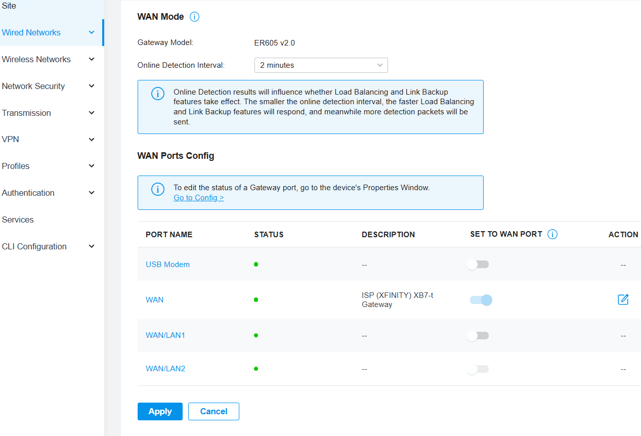 Figure 1: Example of labeling the WAN port in Omada Controller.
Configuration Steps
- Adding VLANs:
- Began adding VLANs according to the network subnet plan. This involved defining the corresponding network address, gateway, subnet mask, and DHCP range for each VLAN within the router configuration.
Initially created VLAN 10 using the LAN interface
WAN/LAN2, as shown conceptually in Figure 2, and saved the configuration.- Note: After completing steps 1-6 Note: After initial configuration phases and encountering testing issues (detailed in Testing Techniques > Troubleshooting > #1), VLAN 10 was ultimately deleted and replaced with VLAN 11 due to connectivity issues encountered during testing.
- Inside the OC, configured the “Interfaces” option rather than “VLAN” as the “Purpose” setting, following guidance from manufacturer support resources. This is necessary to assign the subnet, DHCP range, and other required network parameters.
- Other optional features were left unconfigured at this stage to first establish and verify basic functionality.
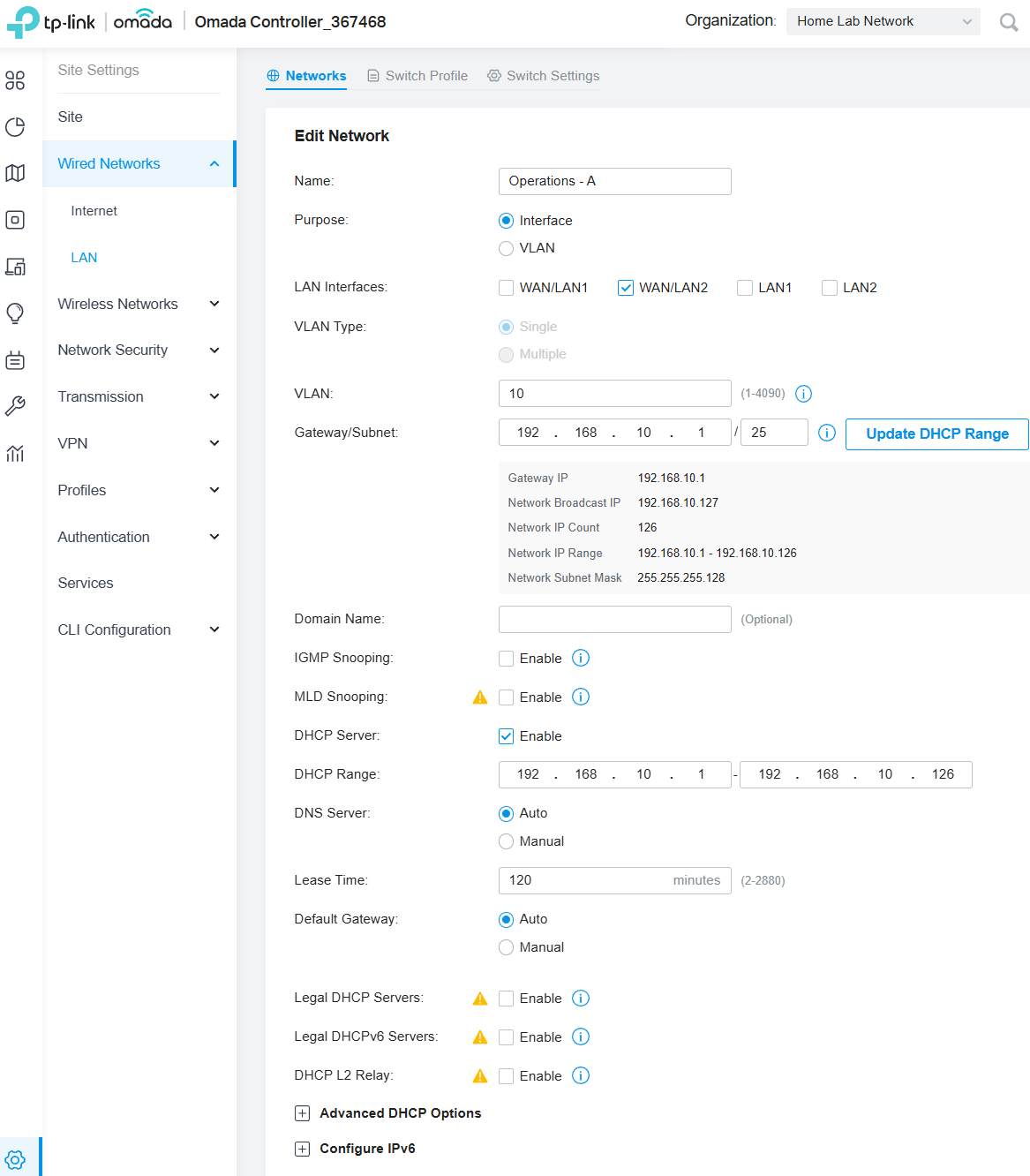 Figure 2: Conceptual view of the VLAN configuration interface.
 - Changing LAN Port Assignment:
- After initially assigning port
WAN/LAN2as the LAN interface for VLAN 10, I decided to useLAN1Port instead. The physical location ofLAN1on the router better suited the cabling layout for connecting devices. - Edited the VLAN 10 configuration, changed the interface setting to
LAN1, saved the changes, and proceeded to configure the remaining VLANs. Figure 3 shows an overview page reflecting the completed VLAN setup.
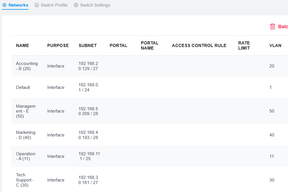 Figure 3: Overview page showing all configured VLANs.
 - After initially assigning port
- Addressing Port Connectivity Issues:
- This change revealed connectivity issues later When switchingthe trunk cable from the router’s
WAN/LAN2port to theLAN1port, all VLANs had connectivity except VLAN 10, despite the interface setting having been updated in the router (see Testing Techniques > Troubleshooting #1).
- This change revealed connectivity issues later When switchingthe trunk cable from the router’s
- Reviewing Switch Profile Settings:
- Next, reviewed the settings under Wired Networks > LAN > Switch Profile. This page contains the VLAN Tag settings for switch ports managed by the Omada Controller.
- When the VLANs were created (in Step #1), corresponding “Switch Profiles” were automatically generated by the router.
- Problem Identified: The auto-generated profiles for the VLANs had their Native Network set to Default(1) (indicating the trunk port setting) and the Untagged Networks included both the corresponding VLAN ID (e.g., 10, 20, 30) and Default(1). This default configuration (shown conceptually in Figure 4) is incompatible with the intended two-router and switch setup for correct traffic routing.
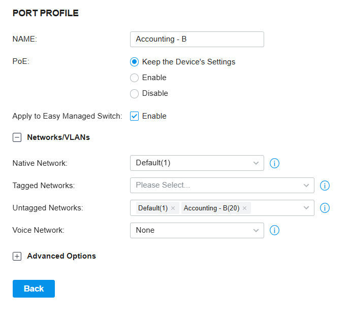 Figure 4: Example of incompatible auto-configured switch profile settings.
- Explanation: The Native Network determines the Port VLAN Identifier (PVID) for a switch port. When a port receives an untagged frame, the switch adds a VLAN tag based on the PVID and forwards the frame within that native network. Therefore, for access ports, the Native Network should be set to the specific VLAN’s PVID, not Default(1). Similarly, the Untagged Networks setting for an access port should typically only include the specific VLAN ID it belongs to, not Default(1).
- Solution: It was not possible to save the necessary changes by directly editing the auto-created switch profiles. Therefore, I had to delete all the auto-generated profiles and manually create a new profile for each VLAN with the correct settings (Native Network = VLAN ID, Tagged Networks = None, Untagged Networks = VLAN ID). See Figure 5 for an example of correctly configured settings for a VLAN profile.
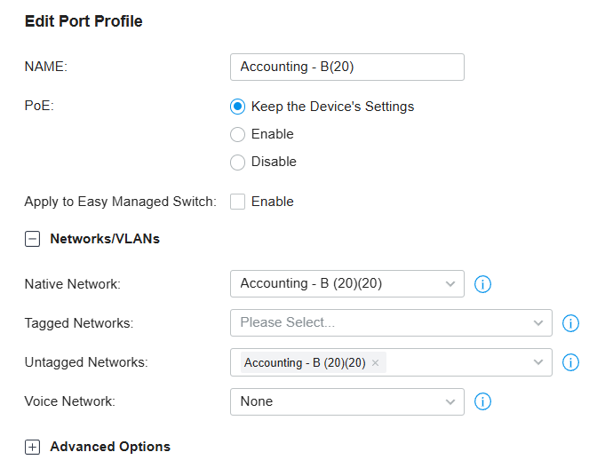 Figure 5: Example of correctly configured switch profile settings.
 - Integration with Managed Switch:
- After completing the router’s VLAN and switch profile configurations, the Xnyahitog XY-M2F8P managed switch was configured with the corresponding VLANs. This aligned the switch with the network plan designed to isolate different “departments” (represented by VLANs) for security while still allowing necessary inter-VLAN communication. (Refer to the separate Xnyahitog XY-M2F8P managed switch Configuration and Testing Guide for details on the switch setup).
Testing Techniques
General Testing Guidelines
- Router Configuration: Access the router’s web interface (via Omada Controller in this case) from a computer directly connected to a LAN port (initially, the default LAN might be easiest before VLANs are fully active). Complete the necessary settings: VLANs, DHCP scopes, Inter-VLAN Routing rules, etc.
- Connecting Computers After Configuration: Only after completing the configuration on both the router and the switch should you connect end devices (computers, servers, etc.) to their designated VLAN ports on the switch. This methodical approach helps isolate potential issues to configuration steps rather than complicating troubleshooting with potential cabling or hardware faults.
- Switch Configuration: Access the managed switch’s web interface from a computer directly connected to one of its ports. Configure the corresponding VLANs and assign these VLANs to specific switch ports (access ports). Set up the trunk port (connecting to the router) to carry tagged traffic for all VLANs, as outlined in the Xnyahitog XY-M2F8P switch tutorial.
- Perform Connectivity Tests:
- Ping Tests: Test connectivity between computers on the same VLAN and then between computers on different VLANs (to verify inter-VLAN routing).
- Network Services: Verify that DHCP is correctly assigning IP addresses, subnet masks, and gateway information appropriate for each computer’s assigned VLAN.
- Internet & Inter-VLAN Access: Ensure devices on each VLAN can access the internet (via the router) and communicate with devices on other VLANs as permitted by the configuration.
- Useful PowerShell and Command Prompt Commands Used:
ipconfig /all: Verify IP address, subnet mask, gateway, DNS, and MAC address on the test PC.ping <IP_address_or_hostname>: Test basic layer 3 connectivity to other devices, the gateway, or internet addresses.tracert <IP_address_or_hostname>: Trace the network path packets take to a destination, helpful for diagnosing routing loops or failures.netsh: A powerful command-line utility for viewing and configuring various network settings.netsh winsock reset: Resets the Winsock Catalog to a clean state (often requires reboot).netsh int ip reset: Resets the TCP/IP stack (often requires reboot).netsh advfirewall reset: Resets the Windows Firewall configuration to default.
Restart-NetAdapter -Name "Ethernet 2"(PowerShell): Restarts a specific network adapter. Replace"Ethernet 2"with the actual name.Restart-NetAdapter -Name "E*2"(PowerShell): Restarts network adapters matching a wildcard pattern.ipconfig /flushdns: Clears the local DNS resolver cache.ipconfig /release: Releases the current DHCP-assigned IP address lease.ipconfig /renew: Requests a new IP address lease from the DHCP server.
Troubleshooting & Key Learnings
1. VLAN 10 Connectivity Issues
- Symptom: Devices connected to switch ports assigned to VLAN 10 could not obtain an IP address or communicate on the network after the physical trunk port was moved from
WAN/LAN2toLAN1. - Steps Taken: I double-checked all settings, rebooted devices, deleted and recreated the VLAN 10 configuration, and even contacted TP-Link support, who suggested a factory reset.
- Solution: Before resorting to a factory reset, I attempted one final approach:
- Deleted the problematic VLAN 10 configuration entirely from both the router and the switch.
- Created a new VLAN using a different ID, VLAN 11, with the same intended network settings.
- Reconfigured the switch profile and switch port assignments for the new VLAN 11.
- Rebooted both devices. This resolved the connectivity issue.
2. Key Learnings & Takeaways
This project provided several practical learning experiences beyond standard configuration:
- “Ghost” Configurations Can Exist: The VLAN 10 issue highlighted that network devices can sometimes retain a problematic state or ‘ghost’ configuration related to a specific ID that isn’t cleared by simple reconfigurations or reboots. Circumventing the problematic element by using a new identifier (VLAN 11 instead of 10) was a highly effective troubleshooting step before resorting to a complete factory reset, saving significant time.
- Verify Auto-Generated Settings: I learned not to implicitly trust automatically generated configurations. The “Switch Profiles” created by the Omada Controller were incompatible with my network design and required manual deletion and recreation. This emphasizes the importance of verifying every setting, even those created by the system.
- Methodical Testing is Essential: The process of testing each VLAN individually after configuration changes was crucial for isolating the problem to a single VLAN, which greatly narrowed the scope of troubleshooting.