Home Lab Network - Planning, Design, and Infrastructure
Project Origin: This project was undertaken as part of the “Special LAN Projects” elective during my academic program. It involved the complete lifecycle from hardware selection and preparation to OS installation, network configuration, and comprehensive documentation.
Introduction
Every successful network deployment begins with a solid plan. This document outlines the crucial logical planning and design phase of my home lab project, which serves as the foundation for all subsequent configuration guides in this series. It covers the project’s goals, the logical network design—defining the high-level topology, IP addressing scheme, and VLAN structure—and the physical infrastructure setup, from hardware selection to the creation of custom network cables.
This guide is intended to showcase the foresight and methodology required to build a network from the ground up, providing context for the hands-on configurations detailed in later posts.
Project Goals & Requirements
The primary objective of this project was to move beyond theoretical knowledge and gain practical, hands-on experience with technologies and concepts relevant to enterprise IT environments. The specific goals were:
- Build a Functional, Segmented Network: To create a stable, multi-VLAN network that simulates a small business environment, providing a platform for safe experimentation.
- Gain Enterprise Technology Experience: To install, configure, and manage key infrastructure components, including:
- A Type-1 hypervisor (Proxmox VE).
- Windows Server 2022, including Active Directory Domain Services (AD DS), DNS, and Group Policy Objects (GPO).
- Managed switches and VLAN-aware routers.
- Develop Real-World IT Skills: To practice tasks directly applicable to IT support and administration roles, such as troubleshooting network connectivity, managing user accounts, and simulating end-user support scenarios.
- Establish a Foundation for Future Learning: To create a robust local network that can be expanded upon for future projects, including the integration of a hybrid cloud environment using Microsoft Azure and Intune for cloud management practice. This demonstrates a commitment to continuous learning and skill development.
Logical Network Design
The logical design defines how data flows across the network, including IP addressing, subnetting, and traffic segmentation.
1. IP Addressing and Subnet Plan
A detailed subnet plan was created to ensure efficient use of IP addresses and logical separation between departments. Each VLAN was assigned a unique subnet.
| VLAN ID | Department Name | Network Address | Subnet Mask | Gateway | DHCP Range |
|---|---|---|---|---|---|
| 1 | Management | 192.168.0.0/24 | 255.255.255.0 | 192.168.0.1 | 192.168.0.100-150 |
| 10 | Operations | 192.168.10.0/25 | 255.255.255.128 | 192.168.10.1 | 192.168.10.10-50 |
| 20 | Accounting | 192.168.20.128/27 | 255.255.255.224 | 192.168.20.129 | 192.168.20.135-150 |
| 30 | Marketing | 192.168.30.160/27 | 255.255.255.224 | 192.168.30.161 | 192.168.30.170-180 |
| 40 | Tech Support | 192.168.40.192/28 | 255.255.255.240 | 192.168.40.193 | 192.168.40.195-205 |
| 50 | Management Dept | 192.168.50.208/28 | 255.255.255.240 | 192.168.50.209 | 192.168.50.212-220 |
Understanding Subnetting: The Apartment Building Analogy
Think of your network as an apartment building with a postal system:
Local Delivery (Same Subnet)
If you live in apartment 1 and want to send a note to apartment 3, you wouldn’t use the post office because the note doesn’t need to leave the building. You can deliver it directly within the building.
Similarly, when 192.168.1.5 wants to send data to 192.168.1.8, both computers are on the same network (192.168.1.0 with subnet mask 255.255.255.0). The data stays within the local network segment—no router needed.
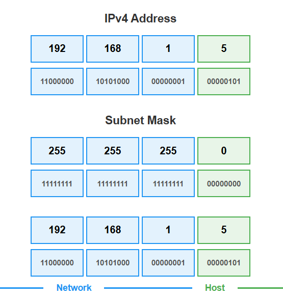 Figure 1: Basic IP address structure showing network and host portions using 192.168.1.5/24
External Delivery (Different Subnets)
If you want to send a payment to the cable company down the street, you must use the postal service (your router). The postal service looks at the full address, notices the zip code is local, and delivers it directly to the cable company.
When 192.168.1.5 sends data to 192.168.30.15, the subnet mask tells the computer these are different networks. The packet goes to the router, which forwards it to the correct destination network.
How Subnet Masks Work
The subnet mask acts like the building’s address system. It tells computers where the “network address” ends and where the “host address” begins:
- Network portion (the 1s in binary): Defines the “building” or network segment
- Host portion (the 0s in binary): Defines individual “apartments” or devices
Example:
- IP Address:
192.168.1.5 - Subnet Mask:
255.255.255.0(or/24) - Network Address:
192.168.1.0(the “building”) - Host Address:
.5(the “apartment number”)
Variable Length Subnet Masks (VLSM)
Just like dividing a large apartment building into smaller sections for security or organization, we can create smaller subnets by “borrowing” bits from the host portion:
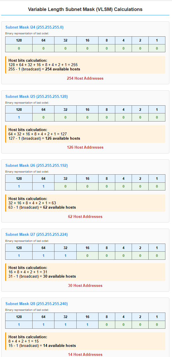 Figure 2: Variable Length Subnet Mask calculations showing available hosts for different subnet sizes
Common subnet sizes:
/24(255.255.255.0): 254 available hosts (large building)/25(255.255.255.128): 126 available hosts (half the building)/26(255.255.255.192): 62 available hosts (quarter of the building)/27(255.255.255.224): 30 available hosts (small wing)/28(255.255.255.240): 14 available hosts (small office suite)
CIDR Notation
Instead of writing out the full subnet mask, we use CIDR notation—a shorthand that shows how many bits are used for the network portion:
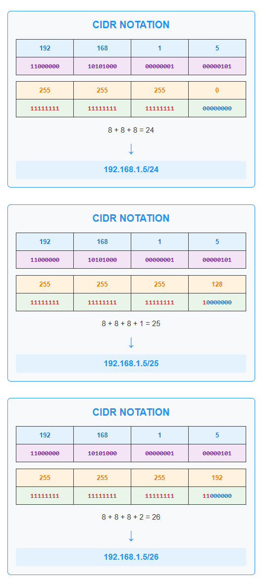 Figure 3: CIDR notation examples showing how /24, /25, and /26 relate to subnet masks
Examples:
192.168.1.5/24means 24 bits for network, 8 bits for hosts192.168.1.5/25means 25 bits for network, 7 bits for hosts192.168.1.5/26means 26 bits for network, 6 bits for hosts
Why This Matters for VLANs
Each VLAN in our network design represents a different “building” or department:
- Management VLAN (
192.168.0.0/24): Large building with 254 possible devices - Tech Support VLAN (
192.168.40.192/28): Small office suite with only 14 possible devices
This logical separation provides security (departments can’t directly access each other) and efficient IP address usage (smaller departments get smaller address spaces).
2. VLAN Strategy
The VLAN strategy was designed to simulate a small business environment, providing traffic segmentation for security and manageability. This structure also provides a realistic framework for practicing the application of Group Policies and administrative delegation in later project phases.
3. Network Topology Diagram
The following topology was designed using Cisco Packet Tracer to visualize the network layout. It illustrates the relationship between the ISP gateway, the primary TP-Link router (which performs inter-VLAN routing), the Xnyahitog managed switch (which handles Layer 2 VLAN segmentation), and the end-user devices in their respective VLANs.
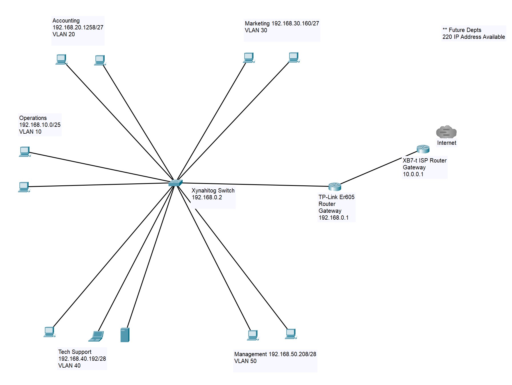 Figure 4: The planned network topology, showing the flow from the internet to the segmented VLANs.
Physical Infrastructure
The physical design covers the hardware and cabling that form the backbone of the network.
1. Hardware Selection
The following core components were selected for the initial build of the home lab:
- Router: TP-Link ER605 Multi-WAN VPN Router
- Switch: Xnyahitog XY-M2F8P Managed Switch
- Hypervisor Host: A repurposed laptop which I upgraded the HD to an SSD as well as increasing the amount of RAM for the purposes of installing and running Proxmox VE.
- Client Devices: Various PCs and VMs running Windows 10 and 11 as well as Linux distributions.
2. Network Cabling: T568B Straight-Through
To ensure reliable connectivity and to practice a fundamental networking skill, all necessary Ethernet patch cables were custom-made. The process involved measuring the required length for each connection, cutting the CAT 6 UTP (Unshielded Twisted Pair) cable, and terminating each end with an RJ45 connector. The T568B wiring standard was used for all cables to maintain consistency, which is the most common standard for straight-through cables in modern networks.
Key Steps Followed:
- Stripping the Cable: Approximately 1.5 inches of the outer jacket was carefully stripped to expose the four twisted pairs of wires.
- Ordering the Wires: The pairs were untwisted and meticulously arranged according to the T568B color code: Orange/White, Orange, Green/White, Blue, Blue/White, Green, Brown/White, Brown.
- Preparing for Crimping: The arranged wires were flattened and trimmed to about 0.5 inches, ensuring they were all of even length.
- Inserting and Crimping: The wires were carefully inserted into the RJ45 connector, ensuring each wire was in its correct pin slot and that the outer jacket was securely inside the connector’s base. A crimping tool was used to firmly secure the connector.
- Testing: Each finished cable was tested with a network cable tester to verify continuity and correct pinout.
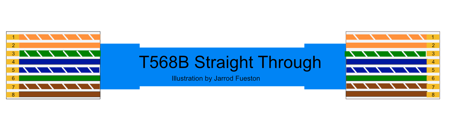 Figure 5: The T568B color code standard used for all patch cables.
Conclusion
With the logical design defined, the physical hardware selected, and the infrastructure cabling in place, the foundational planning phase of the home lab project was complete. This methodical approach ensured that all subsequent configuration stages had a clear and well-defined roadmap to follow.
The next step in this series is the configuration of the core network hardware, starting with the managed switch.
Next Guide: Configuring the Xnyahitog XY-M2F8P Managed Switch