Configuring the Xnyahitog XY-M2F8P Managed Switch for a Home Lab Network
Introduction
This post outlines the steps I used to configure and set up the Xnyahitog XY-M2F8P managed switch for my home lab network. It covers the initial setup, VLAN configuration, and integration with the TP-Link router and the primary ISP XB7-t Router.
I had acquired this switch before it became clear that an additional router (the TP-Link) would be necessary to achieve the home lab network objectives. This was due to most advanced features on the ISP-provided router being locked down and non-configurable. Consequently, the switch was first connected directly to the ISP router for initial testing and to verify its basic functionality before its return window closed. This guide details the configuration process, including troubleshooting steps encountered.
Equipment & Network Overview
- ISP Gateway: XB7‑t (
10.0.0.0/24) - Router: TP‑Link (
192.168.0.1; DHCP for VLANs 11–50) - Switch: Xnyahitog XY‑M2F8‑P (configured to 192.168.0.2)
- Test PCs: Windows 11, Windows 10, Linux Ubuntu (DHCP/static as needed)
VLAN plan (logical):
- VLAN 1 (native/management)
- VLAN 11: Operations A
- VLAN 20: Accounting B
- VLAN 30: Marketing C
- VLAN 40: Tech Support D
- VLAN 50: Management E
Understanding VLANs: A Quick Review
VLAN configurations can sometimes be confusing. Before we dive into the specific setup for the Xnyahitog switch, here’s a quick review of some key terms and concepts that are fundamental to this process:
| Term | Description |
|---|---|
| VLAN ID / Tag / PVID | A unique numerical identifier inserted into Ethernet frames to specify the Virtual LAN they belong to. The PVID (Port VLAN ID) is the VLAN ID assigned to untagged traffic arriving on a switch port. |
| Untagged Traffic | Ethernet frames that do not contain a VLAN tag. Devices like standard PCs or printers typically send untagged traffic. A switch port configured for an untagged VLAN will assign incoming untagged frames to its PVID. This is often referred to as an “access port” for that VLAN. |
| Tagged Traffic | Ethernet frames that include a VLAN tag. Tagged traffic is used on links between network devices that need to carry traffic for multiple VLANs (e.g., switch-to-switch or switch-to-router links). |
| Trunk Port | A switch port configured to carry traffic for multiple VLANs simultaneously. Trunk ports typically send and receive tagged frames for most VLANs, but can also have one untagged VLAN, known as the “native VLAN.” In a home/small office setup, the link from a VLAN-aware router to a managed switch is a trunk. |
VLAN ID / Tag: VLANs allow you to create multiple logical (virtual) local area networks on top of a single physical network infrastructure. Each VLAN behaves as a separate broadcast domain. This is achieved by adding a “tag” (the VLAN ID) to the Ethernet frames. This tag allows switches and routers to identify which VLAN a particular frame belongs to, enabling them to group devices logically regardless of their physical connection point.
Untagged (Native) VLANs Overview: When you configure a switch port with an “untagged” VLAN (by setting its PVID and configuring the port mode as access/untagged for that VLAN), you are telling the port which VLAN any untagged traffic arriving on that port should belong to. Most end-user devices (like desktop PCs, printers) are not VLAN-aware and send untagged frames. When such a device is plugged into a port, the switch assigns its traffic to the PVID of that port. For example, if Port 5 has a PVID of 20, any untagged device plugged into Port 5 will become part of VLAN 20.
Tagged VLANs Overview: On a trunk port, you typically configure multiple VLANs as “tagged.” This means the port will accept incoming frames already tagged for those VLANs and will add the appropriate tag to outgoing frames for those VLANs. For instance, a VoIP phone might be configured to tag its own traffic for VLAN 30 (the voice VLAN). When this phone is connected to a switch port that is configured to accept tagged traffic for VLAN 30 (and perhaps has a different untagged/native VLAN for a PC connected to the phone’s pass-through port), the phone’s traffic is correctly routed to the voice VLAN.
To help you visualize the process, here is a useful Analogy:
- Imagine an office building (the physical network):
- A visitor with no specific destination (untagged device) arrives at the front door (switch port) and is directed to the general lobby (the port’s PVID/untagged VLAN).
- A visitor with an appointment for “Suite 30” (device sending tagged traffic for VLAN 30) arrives at the same front door (trunk port). The receptionist (switch) checks their tag and directs them to Suite 30 (VLAN 30). The front door itself must be able to handle people going to many different suites (multiple tagged VLANs).
Initial Setup
Initial Planning and Preparation:
- Reviewed manufacturer manuals and VLAN documentation.
- Planned tagging and VLAN configurations for both router and switch.
Determining Port and VLAN Placement:
- Planned port assignments based on the physical topology documentation, device and cabling layout.
- As a result, the port assignments discussed later might not appear in strictly chronological order relative to the VLAN PVID setup sequence.
Issues Accessing the Switch User Interface (UI):
- Initially could not access switch UI through provided IP (full details in Troubleshooting section #1).
Solution Summary:
- Set PC to a static IP address within the switch’s default subnet (
192.168.0.0/24). - Changed switch IP settings from DHCP to static, selecting an available IP address within the ISP router’s subnet (
10.0.0.0/24). - Reserved this static IP in the ISP router using the switch’s MAC address.
- Returned PC network adapter settings to DHCP, restoring internet and switch UI access.
- Later updated switch IP settings to match the
192.168.0.0/24network after integrating the TP-Link router.
Verifying Basic Switch Functionality:
- Verified internet connectivity and inter-port device communication using network utilities,
pingandtracert, from connected devices on the network.
- Verified internet connectivity and inter-port device communication using network utilities,
All ports should respond to ping before moving on
Configuration Steps
Connecting to TP-Link Router:
- Connected ISP router to TP-Link router primary WAN port.
- Connected TP-Link router to switch port 1 (trunk port) to carry tagged VLAN traffic from the router.
Adding VLAN Static Table Settings:
- At this stage, the necessary VLANs had already been created and configured on the TP-Link Router (for more details see: TP-Link Router Configuration Guide). The next step was to mirror these VLANs on the Xnyahitog switch.
- Accessed the static VLAN Table settings by navigating to Configuration > VLAN > Static VLAN in the switch’s web UI.
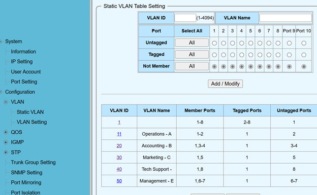 Figure 1: Static VLAN table settings.
- In addition to adding to the table to permanently save these settings it was necessary to navigate to Tools > Save > Save Configuration.
While the above setup works, I later learned that in enterprise environments access ports 2–8 are normally set to Not Member of VLAN 1 instead of tagged—making each port’s membership explicit and reducing misconfiguration risk.
VLAN Port Settings:
- Set Port VLAN IDs (PVIDs) under Configuration > VLAN > VLAN Setting.
- Configured trunk port as tag-only, access ports (2-8) as untag-only (Figure 2).
- Again, these settings were permanently saved via Tools > Save > Save Configuration.
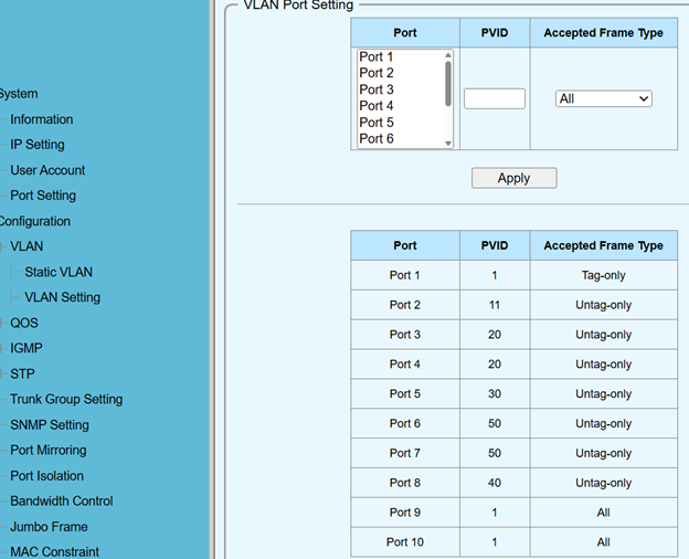 Figure 2: VLAN port settings.
Tested VLAN Configuration:
- Plugged devices into ports (2-8), verified correct VLAN IP assignments.
- Ensured VLAN isolation, allowing communication only when explicitly permitted.
- see more detailed testing explanation next section
Testing Techniques
General Testing Guidelines
To verify proper VLAN configuration and connectivity:
ipconfig /all(on Windows) orifconfig/ip addr(on Linux): To verify the IP address, subnet mask, default gateway, and DNS server settings on test devices connected to various VLAN ports.ping <target_IP>:- Ping the default gateway IP for the VLAN the device is on.
- Ping another device on the same VLAN.
- Ping a device on a different VLAN (to test inter-VLAN routing if enabled on the router, or confirm isolation if not). * Ping an external internet address (e.g.,
8.8.8.8or a website) to confirm internet connectivity.
tracert <target_IP>(on Windows) ortraceroute <target_IP>(on Linux): To trace the path network traffic takes to a destination. This is useful for diagnosing routing issues, especially for inter-VLAN or internet traffic.ipconfig /flushdns: To clear the local DNS resolver cache if encountering DNS-related issues.ipconfig /releasefollowed byipconfig /renew: To force the DHCP client to release its current IP address and request a new one from the DHCP server (useful for confirming DHCP assignment per VLAN).
Troubleshooting
- Connecting to the Switch UI Through ISP Router (Initial Problem):
- Symptom: Unable to access the switch’s web UI using its default IP (e.g.,
192.168.0.1) when connected to the ISP router. - Initial Checks:
- Verified the issue wasn’t with web browser settings by trying different browsers.
- Tried incognito/private mode to rule out extensions.
- Ensured any “Force HTTPS” browser settings were disabled for the switch’s IP.
- Network Diagnostics:
- Attempted to
pingthe switch’s default IP—timed out. - Attempted to
pingthe ISP router’s gateway IP—succeeded, confirming basic PC-to-ISP-router connectivity.
- Attempted to
- Cause Identification:
The switch was on192.168.0.0/24while the PC and ISP router were on10.0.0.0/24.
Devices on different IP subnets cannot communicate directly without a router facilitating the communication.
- Symptom: Unable to access the switch’s web UI using its default IP (e.g.,
Resolving Switch Connectivity Issue:
- Step 1: Direct PC-to-Switch Connection & Static IP on PC
- Disconnected the PC from the ISP router/network.
- Connected the PC directly to one of the switch’s LAN ports (e.g., Port 2).
- Manually configured the PC’s network adapter with a static IP address in the switch’s default network range (e.g., IP:
192.168.0.10, Subnet Mask:255.255.255.0, Gateway:192.168.1.1).
- Step 2: Accessing Switch UI & Changing Switch IP
- With the PC on the same subnet, I could now access the switch’s web UI by typing its default IP (e.g.,
http://192.168.0.6) into a browser. - Navigated to the switch’s system IP settings, found under System > IP Setting. Figure 3 shows an example of default switch IP settings.
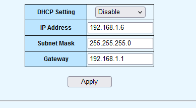 Figure 3: Example of default switch IP settings.
- Selected an unused IP address from the ISP router’s network range (e.g.,
10.0.0.224). I verified this IP was unused by:- Pinging the address from a device already on the
10.0.0.0/24network (ensure no reply). - Checking the
arp -atable on a device on that network. - Reviewing the DHCP client list on the ISP router.
- Pinging the address from a device already on the
- Changed the switch’s IP configuration from DHCP to Static.
- Entered the chosen static IP, (
10.0.0.224), the correct subnet mask (255.255.255.0), and the ISP router’s IP address as the default gateway (10.0.0.1). - Saved these new IP settings on the switch by navigating to Tools > Save > Save configuration. Figure 4 shows the settings entered in the switch UI.
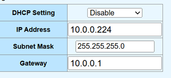 Figure 4: Example of configuring the switch with a static IP on the ISP router’s network.
 - With the PC on the same subnet, I could now access the switch’s web UI by typing its default IP (e.g.,
- Step 3: Reserving IP in ISP Router
- Noted the MAC address of the switch, which can be found on its physical label or within its UI status page.
- Accessed the ISP router’s web UI.
- Navigated to the DHCP reservation (in some routers called static IP assignment or similar) section.
- Reserved the IP address assigned to the switch in previous step (
10.0.0.224) using its MAC address. This ensures the ISP router doesn’t assign this IP to another device. Figure 5 shows a conceptual example.
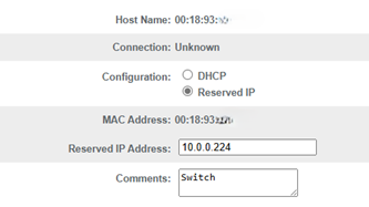 Figure 5: Conceptual example of reserving an IP address for the switch in the ISP router.
 - Step 4: Reverting PC to DHCP & Testing
- Changed the PC’s network adapter settings back to “Obtain an IP address automatically” (DHCP).
- Reconnected the PC to the network through the switch, which was now on the
10.0.0.0/24network. - Confirmed the PC received an IP from the ISP router.
- Successfully accessed the switch’s UI using its new IP (e.g.,
http://10.0.0.224). - Confirmed internet connectivity and basic communication between switch ports.
- Step 1: Direct PC-to-Switch Connection & Static IP on PC
TP-Link Router Integration and IP Adjustment:
- Once the TP-Link router (using
192.168.0.0/24for its LAN) was integrated as the primary router for the home lab:- It became necessary to change the switch’s static IP address again to be on this new
192.168.0.0/24subnet, as the TP-Link router would now be its gateway and DHCP server for the VLANs. - Repeated the process from Troubleshooting #2, Step 2:
- Accessed the switch UI using its then-current IP,
10.0.0.224. - Changed the switch’s static IP to an address in the TP-Link’s LAN range (e.g.,
192.168.0.2). - Set the default gateway on the switch to the TP-Link router’s LAN IP address (e.g.,
192.168.0.1). - Saved the configuration. Figure 6 shows an example of this final IP configuration for the switch with the second router added.
- Accessed the switch UI using its then-current IP,
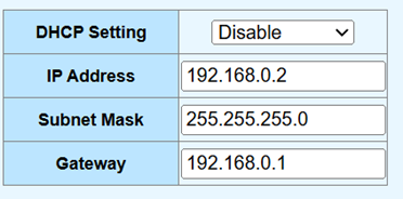 Figure 6: Example of the switch’s final static IP configuration aligned with the TP-Link router’s network.
 - It became necessary to change the switch’s static IP address again to be on this new
- Once the TP-Link router (using
Key Learnings & Takeaways
The Xnyahitog XY-M2F8P managed switch, when correctly integrated with the TP-Link router and the ISP router, provides a robust and flexible foundation for a home lab network. This configuration enables effective VLAN management and network segmentation, which can significantly enhance both security and performance by isolating traffic and controlling communication paths.
I hope you found this useful, if you have any questions, feel free to reach out to me on LinkedIn.