Configuring a Cudy GS1016PE 16-Port Managed Switch
Context: This guide documents an end-to-end hardware upgrade, replacing a previously used Xnyahitog Industrial switch with a Cudy GS1016PE. It details the full configuration process, focusing on implementing enterprise security best practices for VLANs that were discovered during prior projects.
Introduction
This guide documents the setup and configuration of a new Cudy GS1016PE 16-Port Managed Switch in my home lab network. This project serves as both a hardware upgrade and an opportunity to implement more robust, security-focused VLAN configurations based on lessons learned from previous setups. While this guide is a standalone document, it builds upon the network design established in the Xnyahitog Switch Configuration Guide.
The primary goal is to replicate the existing VLAN structure while enhancing security by explicitly defining port memberships and ensuring no traffic can unintentionally “leak” between VLANs.
Equipment & Network Overview
- Router: TP‑Link ER605 (
192.168.0.1; DHCP for VLANs 11–50) - Switch: Cudy GS1016PE (This guide; configured to
192.168.0.2) - Trunk Port: Port 15 (Uplink to TP-Link Router)
VLAN Plan (Logical):
- VLAN 1: Native / Management
- VLAN 11: Operations A (Port 2)
- VLAN 20: Accounting B (Ports 3-4)
- VLAN 30: Tech Support D (Port 5)
- VLAN 40: Marketing C (Port 8)
- VLAN 50: Management E (Ports 6-7)
Understanding VLANs: The Airport Analogy
VLAN configurations, especially the concepts of “Tagged” and “Untagged,” can be confusing. Here’s a simple analogy to clarify how they work together to create a secure, segmented network.
Imagine your network is an airport.
- The switch is the airport’s baggage handling system.
- Data packets are pieces of luggage.
- The VLANs (11, 20, 30, etc.) are the final flight destinations (e.g., Tokyo, London, Paris).
Access Port (e.g., Port 2, for VLAN 11): This is the Economy Class check-in counter for Tokyo. When a passenger (your PC) puts their bag (a normal data packet) on the belt, it has no destination tag. The switch, knowing this is the “Tokyo Counter” (PVID = 11), automatically slaps a “TOKYO” tag (VLAN 11 tag) on the bag. This is why we set an access port as Untagged for its VLAN—it accepts untagged traffic and assigns it to a specific destination.
Trunk Port (Port 15): This is the main sorting conveyor belt going to the airplane (your router). It must carry luggage for all destinations simultaneously. To prevent chaos, every bag on this belt must have a clear destination tag. This is why the trunk port is set as Tagged for VLANs 11, 20, 30, 40, and 50. It only deals with bags that are already tagged for a specific destination.
The “Native” VLAN (VLAN 1 on the Trunk Port): What about the airport crew’s luggage? Their gear isn’t going to a final destination; it’s for managing the airport itself. By agreement, any bag on the main conveyor that has NO tag is assumed to be local crew luggage. This is why the trunk port is Untagged for VLAN 1. It tells the switch, “If any untagged traffic shows up on this trunk link, it belongs to our network management VLAN (not to be confused with VLAN 50 labeled Management in our logical plan).”
Initial Setup
- Gaining Access:
- Connect a computer directly to one of the switch’s LAN ports (e.g., port 1).
- Manually configure your computer’s IP address to be on the switch’s default subnet (e.g., IP:
192.168.0.10, Subnet Mask:255.255.255.0). - Open a web browser and navigate to the switch’s default IP, typically
http://192.168.0.1. - Log in with the default credentials (e.g.,
admin/admin) and change the password when prompted.
Warning: Changing the default login username and password on any new device your configuring should always be your first task. It is an essential best practice to secure the network.
- Configuring Management IP:
- Navigate to System Manage → IP Settings.
- Set the switch’s IP address to match your network plan (e.g.,
192.168.0.2). - Set the Default Gateway to your router’s IP address (
192.168.0.1). - For DNS server, set it to your router’s IP address (
192.168.0.1). This allows the switch itself to resolve names for tasks like firmware updates. - Click Apply.
Tip: After applying a new IP address, you will lose connection to the switch UI. You must reconfigure your computer’s IP address to be on the same new subnet to log back in.
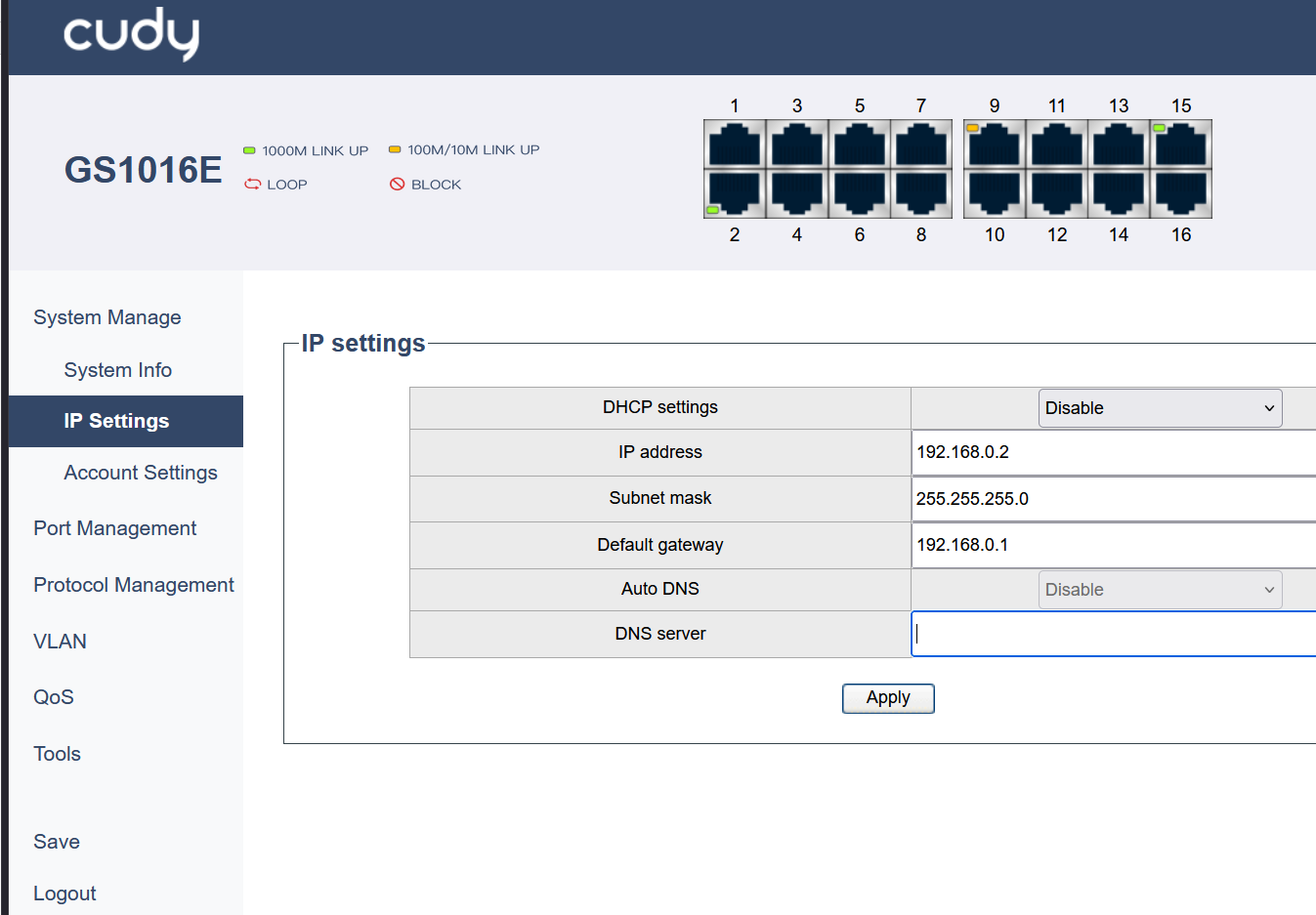 Figure 1: Configuring the switch’s static management IP address.
Configuration Steps
Warning: The following steps must be performed in the correct order. You must create the VLANs and configure their port membership before assigning PVIDs to ports. Attempting to assign a PVID for a VLAN that doesn’t exist yet will result in an error and may cause you to lose access to the switch UI if you are configuring the port you are currently connected through.
1. Enable 802.1Q VLAN Mode
- Navigate to VLAN → 802.1Q VLAN → 802.1Q VLAN Settings.
- Select the Enable radio button for “802.1Q VLAN enabled” and click Apply.
A warning pop-up will appear. Click OK to proceed.
802.1Q vs. Port-Based VLAN: We are using 802.1Q VLAN (also known as tag-based VLAN) because it’s the standard that allows a single link (our trunk port) to carry traffic for multiple VLANs simultaneously by tagging the data packets. The simpler “Port-based VLAN” mode does not use tags and cannot support a trunk port; it can only assign each port to one VLAN, completely isolating it from all others.
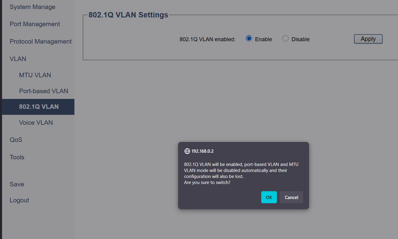 Figure 2: Enabling 802.1Q VLAN mode, which is required for a trunking setup.
2. Create VLANs and Configure Port Membership
On the same 802.1Q VLAN Settings page:
- Create the VLANs:
- In the 802.1Q VLAN field, enter
11. - In the Description field, enter a name like
Operations_A. - Click Add/Edit.
- Repeat this process to create VLANs 20, 30, 40, and 50 with their respective descriptions.
- In the 802.1Q VLAN field, enter
- Configure Port Membership:
- Tip: An efficient way to configure this is to first select a VLAN, check the “Select All” box for Non-member port, and then individually change the ports that need to be
TaggedorUntagged. - For VLAN 1 (the default):
- Port 15 (Trunk): Set to Untagged.
- All other ports (1-14 & 16): Set to Non-member.
- Click Add/Edit.
- For VLAN 11:
- Port 15 (Trunk): Set to Tagged.
- Port 2 (Access Port): Set to Untagged.
- All other ports: Set to Non-member.
- Click Add/Edit.
- Continue this pattern for all other VLANs (20, 30, 40, 50), setting Port 15 to
Tagged, the designated access port(s) toUntagged, and all other ports toNon-member.
 Figure 3: Example configuration for VLAN 50, showing ports 6 & 7 as Untagged (access) and port 15 as Tagged (trunk).
 - Tip: An efficient way to configure this is to first select a VLAN, check the “Select All” box for Non-member port, and then individually change the ports that need to be
3. Set Port PVIDs and Ingress Filtering
- Navigate to the 802.1Q Port Settings section.
- Configure the PVID and Ingress filter for each port:
- Port 1: PVID
1, Ingress filterEnable. - Port 2: PVID
11, Ingress filterEnable. - Port 3: PVID
20, Ingress filterEnable. - Port 4: PVID
20, Ingress filterEnable. - …Continue repeating this process this process for all other access ports, assigning the correct PVID for each department’s VLAN.
- Port 15 (Trunk): PVID
1, Ingress filterEnable. - All Unused Ports: PVID
1, Ingress filterEnable.
- Port 1: PVID
- Click Apply after setting each port, or after setting all of them if the interface allows.
4. Save the Configuration
- Navigate to Save in the main menu.
- Click the Save button to write your running configuration to the startup configuration.
Warning: This step is critical to prevent losing your settings on reboot.
Testing Techniques
To fully validate the new switch configuration, perform the following tests for each configured VLAN:
- Connect Devices: Connected a test computer to each designated access port.
- Verify IP Addressing: On each computer, ran
ipconfigto confirm it received an IP address from the correct DHCP range for its VLAN. - Check Gateway and Internet Connectivity: From each computer, pinged its default gateway (the router’s IP for that VLAN) and then an external address like
8.8.8.8to confirm internet access. - Verify VLAN Isolation: Attempted to ping a device in a different VLAN. As expected, the pings failed, confirming that the VLANs were successfully isolating traffic from each other at Layer 2.
- Confirm Expected Speeds: Ran a browser-based speed test from a device on each VLAN to confirm it was receiving the expected network throughput.
Key Learnings & Takeaways
Upgrading to the Cudy GS1016PE switch provided an opportunity to not just replace hardware but to significantly improve the network’s security posture by applying enterprise best practices.
Explicit is Better Than Implicit: The key takeaway from this project was the importance of explicitly defining a port’s role. By setting all access ports as
Not Memberof VLAN 1 and any other VLAN they don’t belong to, the configuration becomes unambiguous and secure against potential VLAN hopping attacks.Understanding Configuration Dependencies: The process reinforced the strict order of operations required for VLAN setup: a VLAN must exist before it can have members, and a port can only be assigned a PVID for a VLAN that already exists. This logical dependency is crucial to avoid errors and potential lockouts from the switch UI.
The Role of Ingress Filtering: I learned that enabling Ingress Filtering is a critical security step. It ensures that a port only accepts traffic tagged for VLANs it is explicitly a member of, providing a powerful enforcement of the network’s logical boundaries.
Separation of Duties: This project further clarified the distinct roles of a Layer 2 switch and a Layer 3 router. The switch’s job is to enforce segmentation within the LAN using VLANs, while the router’s job is to manage traffic between those VLANs and to the outside world.